Lego robotics basics

In my summer of exploring robotics, one of the first ones I was playing with was the Lego EV3 kit.  There are a lot of good videos out that can help with programming the robots and understanding the variety of sensors that are available.  My go to series was from Kevin Briggs (https://www.youtube.com/watch?v=IuHaIE-auLQ) who has a perfect explanation (with code) to help you with the basics.

The main sensors available are the ultrasonic sensor, gyro-sensor, touch sensors, and the color sensor (this one is tricky because it needs to have “Lego” colors).  The sensors I worked the most with were the ultrasonic and the touch sensors, as I was most curious about makes a self-driving robot that can avoid obstacles.

I had played around with one of these a year before but had a lot of trouble using the sensors that were available.  The biggest thing I noticed from the tutorials is that you need to setup the sensor, and then using a logic statement, you need to make the loop continue or not for autonomy.  Lego has a control setup in the loop structure but I was finding that it would not work appropriately because it was an end loop check rather than a beginning loop check.  For example, it will drive then look for the wall and then drive again, so if it is close to the wall it will crash as opposed to stopping when it gets within a range.  Also it is a lot easier to make the distance check work within the given range with a control statement setup at the start of a loop.

Last year I had students play with the robots to learn how to use them better and the students were unable to make the loops work correctly.  Unfortunately I did not have the time to look at it closer but now I can show them some basic programs that can help with understanding how the robot will move.

Below is an example of a distance sensor in action.  The robot will continue straight unless it is within 10cm of a wall (or object).  The structure is set up that it will check for a distance less than 10cm, if it is within that range, it will reverse and turn left, if it is not, it will drive forward.  This is in a loop so it will go on forever.

legocode

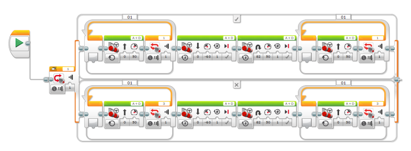
The best way to make a robot to be autonomous with the EV3, is to set it up similar to this.  You simply change the sensor (the yellow) and then the condition (the red), and then make it complete the steps in the true (check-mark) and the false (x) in order to make the robot function endlessly.

I find that this robot is perfect for high school students to learn about robotics and procedural learning because it is easy to use for basic movement, and the software comes pre-loaded with tutorials to teach them how to drive the car and learn the functions.  It is also nice because the students can try to build a better robot with the pieces and even the GyroBoy, that has instructions included in the software.  This is also nicer than Arduino for new learners because it does not require any code to write and is a good progression from scratch (and the hour of code).


Here is the touch sensor code:

legocode2.PNG

Arduino Robot

This summer I decided to have some fun with the various robotics we have at our school.  The first one I worked with was the Arduino microcontroller.  I bought a couple of different quicks from an offshore website (https://www.banggood.com/4WD-Smart-Robot-Car-Chassis-Kits-With-Strong-Magneto-Speed-Encoder-p-917007.html, https://www.banggood.com/2WD-Avoidance-Tracking-Smart-Robot-Car-Chassis-Kit-With-Speed-Encoder-Ultrasonic-For-Arduino-UNO-R3-p-1124282.html) that took a few weeks to arrive, but came with almost all the parts needed (extra wiring was not included, and for the second car I wanted the L298N Motor controller).

It was somewhat tricky to get started, I do not have a background in wiring and electrical work (have wired one Arduino before with a very detailed video) on microcontrollers but this one was not too difficult and has a lot of similar videos that can help.

The trickiest part of the build was linking up the motors to the motor controller and then linking that to the Arduino (or the motor shield, which I have done both now).  The kits do need additional power supplies (the only downside to using the motor control), so I am currently waiting for the 9V battery adapters from Amazon before I can let them drive around my garage freely.

I learned that the fear I had with wiring it wrong was not one I should worry about.  The forgiving part of the arduino is that as long as you identify it correctly in the code as a global variable to the correct pin it will work.  You will need to also connect the ground to the motor and the arduino board ground (on the port side).  The motor controller is beneficial because you can use it to combine motors, change speeds, and provide it with additional power to make it function correctly.  The first car I made had only one power supply to a breadboard and it was unable to work correctly.  Everytime it was connected to the PC is would drive at the right speed and then when connected to battery it would go much faster.

I found the one thing missing from the readings I found was that it did not explain the controllers on the motors easily, so I am labeling it here. Using L298N motor:
– ENA/b controls the speed
– IN1 right motor forward movement if set to high (IN2 must be set to low)
– IN2 right motor reverse movement if set high (IN1 must be set to low)
– IN1 left motor forward movement if set to high (IN4 must be set to low)
– IN2 left motor reverse movement if set high (IN3 must be set to low)
– setting all motors to low will turn it off (like using breaks)

here is the code I have used.

// motor one
int enA = 10;
int in1 = 9;//for
int in2 = 8;//rev
// motor two
int enB = 5;
int in3 = 7;//for
int in4 = 6;//rev

void setup()
{
// set all the motor control pins to outputs
pinMode(enA, OUTPUT);
pinMode(enB, OUTPUT);
pinMode(in1, OUTPUT);
pinMode(in2, OUTPUT);
pinMode(in3, OUTPUT);
pinMode(in4, OUTPUT);
}

void demoOne()
{
// this function will run the motors in both directions at a fixed speed
// turn on motor A
digitalWrite(in1, HIGH);
digitalWrite(in2, LOW);
// set speed to 200 out of possible range 0~255
analogWrite(enA, 200);

// turn on motor B
digitalWrite(in3, HIGH);
digitalWrite(in4, LOW);
// set speed to 200 out of possible range 0~255
analogWrite(enB, 200);

delay(2000);

// now change motor directions
digitalWrite(in1, LOW);
digitalWrite(in2, HIGH);
digitalWrite(in3, LOW);
digitalWrite(in4, HIGH);

delay(2000);

// now turn off motors
digitalWrite(in1, LOW);
digitalWrite(in2, LOW);
digitalWrite(in3, LOW);
digitalWrite(in4, LOW);
}

void demoThree()
{
//left turn
digitalWrite(in1, LOW);
digitalWrite(in2, HIGH);
digitalWrite(in3, HIGH);
digitalWrite(in4, LOW);
analogWrite(enB, 200);
analogWrite(enA, 200);
delay(1000);

//right turn
digitalWrite(in1, HIGH);
digitalWrite(in2, LOW);
digitalWrite(in3, LOW);
digitalWrite(in4, HIGH);
analogWrite(enB, 200);
analogWrite(enA, 200);
}

void loop()
{
demoOne();
delay(1000);
demoThree();
delay(1000);
}

Attached are some photos as well of the designs.  I will post again on this when I have them moving freely.  And I will post about the utlrasonic sensor as well.